Contents
- Contents
- Introduction
- Rigid Body Motions and Homogeneous Transforms
- Forward and Inverse Kinematics
- Velocity Kinematics - The Manipulator Jacobian
- ROS - Robot Operating System
Introduction
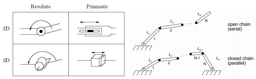
Representations
- Revolute (\theta)- angle
- Prismatic (d) - skalar
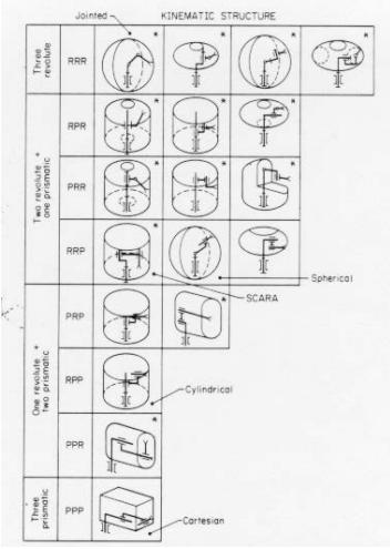
Arm configurations
Definitions
- End-effector/Tool:
- Device that is in direct contact with the environment. Usually very task-specific
- Configuration
- Complete specification of every point on a manipulator
- set of all possible configurations is the configuration space
- For rigid links, it is sufficient to specify the configuration space by the joint angles,
- State space
- Current configuration (joint positions q) and velocities
- Work space
- The reachable space the tool can achieve
- Reachable workspace - max range
- Dextrous workspace - from min -> max range
- The reachable space the tool can achieve
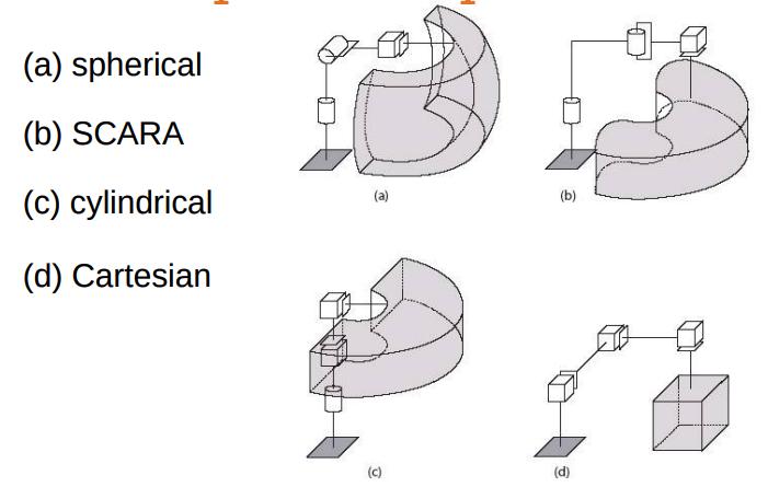
Workspace comparison
Rigid Body Motions and Homogeneous Transforms
Representing Positions
- Superscripts denote reference frames. For example point \(p\) relative to coordinate frame \(o_0x_0y_0z_0\) is written \(p^0\).
- Vectors use the same convention, i.e. \(v_1^0\) is vector 1 relative to coordinate frame 0.
Representing Rotations
Elementary 2D rotation matrix
- Rotation matrix: \(R_1^0 = \begin{pmatrix} cos \theta & -sin \theta \\ sin \theta & cos \theta \end{pmatrix} \)
Elementary 3D rotation matrices
-
Rotation around x-axis: \(R_x(\theta) = \begin{pmatrix} 1 & 0 & 0 \\ 0 & cos \theta & -sin \theta \\ 0 & sin \theta & cos \theta \end{pmatrix} \)
-
Rotation around y-axis: \(R_y(\theta) = \begin{pmatrix} cos \theta & 0 & sin \theta \\ 0 & 1 & 0 \\ -sin \theta & 0 & cos \theta \end{pmatrix} \)
-
Rotation around z-axis: \(R_z(\theta) = \begin{pmatrix} cos \theta & -sin \theta & 0 \\ sin \theta & cos \theta & 0 \\ 1 & 0 & 0 \end{pmatrix} \)
Properties of rotations matrices
- It is orthogonal
- Each column is a unit length vector
- Each column is orthogonal to all other columns
- Dot-product between each column equals 0.
- Inverse same as transpose \(R^{-1} = R^T\)
- Sweet property due to the ease of computing transpose vs Inverse.
- \(det(R) = 1\)
- Length of a vector is unchanged by rotation.
- Belongs to Special Orthogonal group of dimension 3: \(R \in SO(3)\)
Rotational Transformations
- Determining coordinates of \(p\) relative to orientation frame 0 is equal to \(p^1\) multiplied with the rotation matrix \(R_1^0\): \(p^0 = R_1^0p^1\)
- Example of vector \(v^0\) rotated \(\frac{\pi}{2}\) about the y-axis: \(v_1^0 = R_{y, \frac{\pi}{2}}v^0\)
Summary
Rotation matrix of either \(R\in SO(3)\) or \(R\in SO(2)\) can be interpreted in three distinct ways:
- It represents a coordinate transformation relating the coordinates of a point p in two different frames.
- It gives the orientation of a transformed coordinate frame with respect to a fixed coordinate frame.
- It is an operator taking a vector and rotating it to a new vector in the same coordinate system.
Compositions of rotations
- Rotations are non commutative in 3D, this means that the order of which one rotates is critical.
- Rotating R around x-axis then y-axis will not give the same result as rotating around y-axis then x-axis!
- Consecutive rotations w/ respect to the current reference frame:
- Post-multiplying by successive rotation matrices
- w/ respect to a fixed reference frame \((o_0)\)
- Pre-multiplying by successive rotation matrices
- We can also have hybrid compositions of rotations with respect to the current and a fixed frame using these same rules
Example
- Rotation of \(\theta\) around current x-axis
- Rotation of \(\alpha\) around current y-axis
- Rotation of \(\beta\) around fixed z-axis
The cumulative effect of these rotations are \(R = R_{x, \beta}R_{y,\alpha}R_{x,\theta}\).
Parametrizing rotations
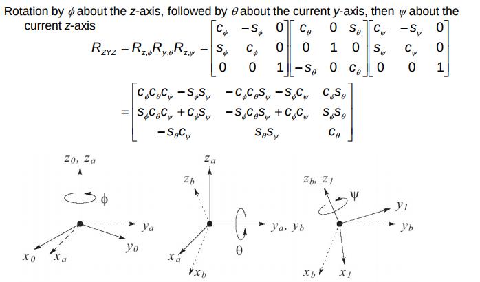
Euler angles
- Rotation theorem: two three-dimensional coordinate frames are related by a sequence of elementary rotations such as those about the x-axis, the y-axis, the z-axis.We need to apply no more than three of those, but the rotations in this sequence need to be about different axes.
- Most typical Euler Angle Transformation is the ZYZ.
- There are two sets of Euler angles which result in the same rotation matrix.
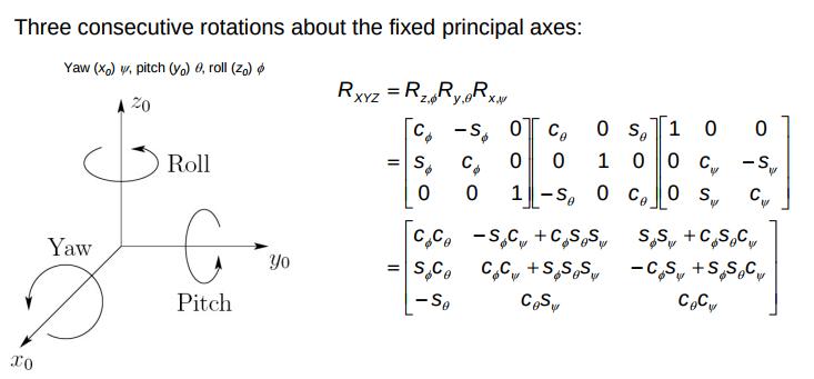
Roll, Pitch, Yaw angles
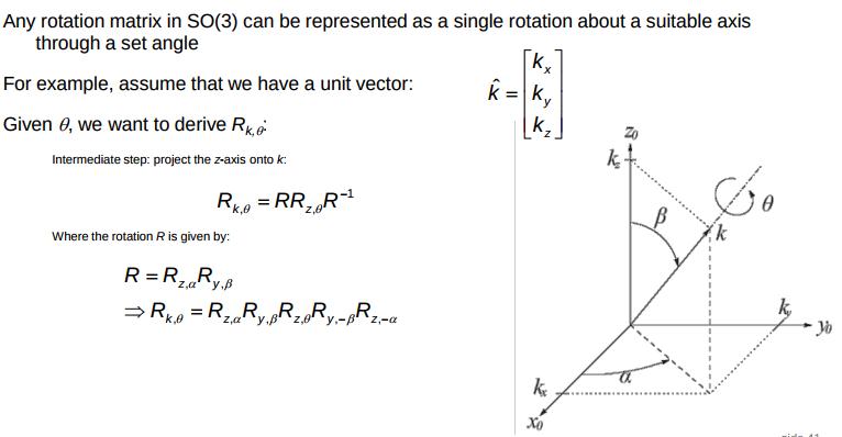
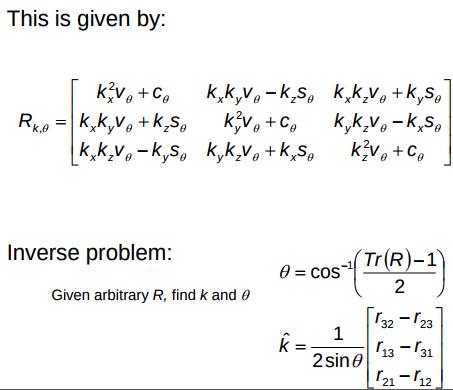
Axis/Angle representation
Rigid Motions
- Position and orientation.
- Defined by rotations matrix \( R \in SO(3)\) and a translation vector \(d \in R^3\)
Homogeneous transformations
- A way of describing translation and rotation i.e. a rigid motion.
- In 3D it has the form: \(H = \begin{bmatrix} R & d \\ 0 & 1 \end{bmatrix}; R \in SO(3), d \in \mathbb{R}^3\)
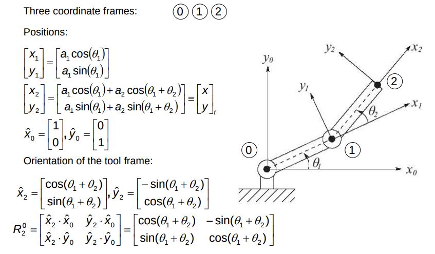
Forward and Inverse Kinematics
“The objective of forward kinematic analysis is to determine the cumulative effect of the entire set of joint variables, that is, to determine the position and orientation of the end effector given the values of these joint variables. The objective of inverse kinematic analysis is, in contrast, to determine the values for these joint variables given the position and orientation of the end effector frame.”
Kinematic Chains
- n joints gives n+1 links.
- Joints are numbered from 1 to n.
- Links are numbered from 0 to n.
- The joint variable denoted \(q_i\) is equal to: \(q_i = \begin{cases} \theta_i & \text{if joint \(i\) is revolute} \\ d_i & \text{if joint \(i\) is prismatic}\end{cases}\)
- Transformation matrix: \(T_j^i = \begin{bmatrix} R_j^i & o_j^i \\ 0 & 1 \end{bmatrix}\)
The objective of forward kinematic analysis is to determine the cumulative effect of the entire set of joint variables, that is, to determine the position and orientation of the end effector given the values of these joint variables. The objective of inverse kinematic analysis is, in contrast, to determine the values for these joint variables given the position and orientation of the end effector frame.
- Tool frame is the coordinate frame attached to the most distal link of the manipulator. \(O_n\)
- Inertial (base) frame is the fixed coordinate system to the most proximal link of the manipulator. \(O_0\)
- Transformation \(o_j) to o_i\) can be defined as: \(T_j^i = \begin{cases} A_{i+1}A_{i+2}...A_{j-i}A_{j} && \text{if i < j} \\\ I && \text{if i = j} \\\ (T_i^j)^{-1} && \text{if j > i}\end{cases}\)
- Position and orientation of tool frame with respect to inertial frame is given by one homogeneous transformation matrix: \(H = \begin{bmatrix} R_n^0 & o_n^0 \\\ 0 & 0 \end{bmatrix} = T_n^0 = A_1(q_1)A_2(q_2)...A_n(q_n)\)
Forward Kinematics: The Denavit-Hartenberg Convention
Representing each individual homogeneous transformation as the product of four basic transformations:
\(A_i = Rot_{z, \theta_j}Trans_{z,d_i}Trans{x,a_i}Rot_{x,\alpha_i}\)
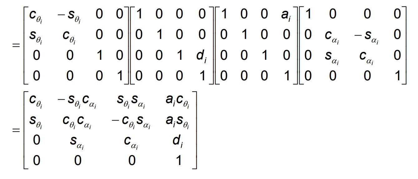
- \(a_i\): link length. Distance between the \(z_0\) and \(z_1\), along the common normal \(x_1\)).
- \(\alpha_i\): link twist, angle between \(z_0\) and \(z_1\) (measured around \(x_1\))
- \(d_i\): link offset. Variable for prismatic joints. Distance between \(z_0\) and intersection of \(z_0\) and \(x_1\) (along \(z_0\)), depth of \(z_{j-1}\) axis to the common normal.
- \(\theta_i\): joint angle. Variable for revolute joints. Angle between \(x_0\) and \(x_1\) (measured around \(z_0\))
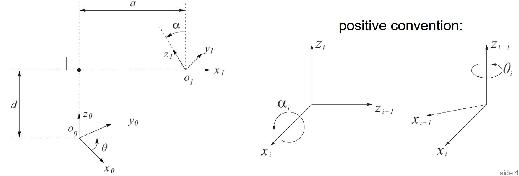
Assigning the coordinate frames
- If joint i+1 is revolute, \(z_i\) is the axis of rotation of joint i+1
- If joint i+1 is prismatic, \(z_i\) is the axis of translation for joint i+1
We have three cases to define coordinate frames:
- \(z_{i-1}\) and \(z_i\) are non-coplanar
- There is a unique shortest distance between the two axes.
- Choose this line segment to be \(x_i\).
- \(o_i\) is at the intersection of \(z_i\) and \(x_i\)
- \(z_{i-1}\) and \(z_i\) intersect
- Choose xi to be normal to the plane defined by \(z_i\) and \(z_{i-1}\).
- \(o_i\) is at the intersection of \(z_i\) and \(x_i\)
- \(z_{i-1}\) and \(z_i\) are parallel
- Infinitely many normals of equal length between \(z_i\) and \(z_{i-1}\).
- Free to choose oi anywhere along \(z_i\), however if we choose \(xi\) to be along the normal that intersects at \(o_{i-1}\), the resulting \(d_i\) will be zero.
Inverse Kinematics
- The problem of finding the joint variables in terms of the end-effector position and orientation.
- May, may not have a solution.
The two most common ways of solving for Inverse Kinematics are * The Analytical solution - Create a model of the system(DH), writing the forward kinematics, solving the equations for the unknown joint variables. * This can be automated, but need some human insight * The Geometrical/Numerical solution * Using trigonometry and geometrical approaches to finding the correct angles and positions.
The General Inverse Kinematics Problem
- Based on a homogeneous transformation matrix $H$, find(one or all) solutions of the equation \(T_n^0(q_1,..,q_n) = H\) where \(T_n^0(q_1,..,q_n) = A_1(q1)...A_n(q_n)\) (q_*) = joint variables.
- Solution in closed form.
Kinematic Decoupling
- For systems with a arm and a wrist.
- Breaking down the robot into two problems and parts:
- Inverse position kinematics: Position of the wrist center
- Inverse orientation kinematics: orientation of the wrist
- We must assume 6DOF with the last three intersecting at \(O_c\)
- Basic how to:
- Extract the center of where the wrist should be
- \[o_6^0(q_1,..,q_n) = o\]
- Find the orientation of the wrist
- \[R_6^0(q_1,..,q_n) = R\]
- Use the position of the wrist center to determine the first three joint angles.
- Extract the center of where the wrist should be
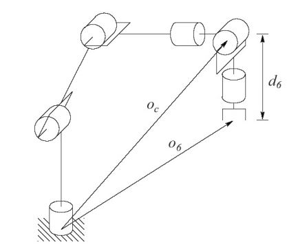
- Tool frame \(o_6\) is a distance \(d_6\) along \(z_5\)
- \(z_3, z_4, z_5\) intersect at \(o_c\)
- \(z_3\) is the end effector of the base, and the first active DOG of the wrist.
Third column of R represents direction of \(z_5, z_6\) in the base frame. Hence:
\[o_c^0 = o - 0 d_6R\begin{bmatrix}0 \\ 0 \\ 1 \end{bmatrix}\]\(\begin{bmatrix} x_c \\ y_c \\ z_c \end{bmatrix} = \begin{bmatrix} o_x - d_6r_{13} \\ o_y - d_6r{23} \\ o_z - d_6r{33} \end{bmatrix}\) Wrist center coords = End effect coords
Note that \(R = R_3^0R_6^3\). The orientation of the end-effector can hence be solved by:
\[R_6^3 = (R_3^0)^-1R=(R_3^0)^TR\]Use Euler angles to solve for them. The rest ar simply trig problems solved with a geometric approach.
Velocity Kinematics - The Manipulator Jacobian
ROS - Robot Operating System
Plumbing
- Nodes are processes that perform executables, i.e they compute something and communicate with other nodes via ROS.
- Topics are data streams that Nodes can subscribe, and or publish to. They are uniquely identifiable by their names.
- Services is a way for Nodes to communicate via sending requests and receive responses.
- Messages are data structures sent between nodes.
- ROS Master is the Node organizer. It provides names and lookup for other Nodes.
Technical Capabilities
- Motion Planning
- Fast and good quality paths
- Kinematic Constraints
- Fast and flexible collision checking
- Integrated Kinematics
- Integrated Perception for Environment Representation
- Standardised Interfaces to Controllers
- Execution and Monitoring
- Kinematic Analysis
- Simulated Robots
Motion Planning
One can apply the following kinematic constraints:
- Position constraints - restrict the position of a link to lie within a specified workspace.
- Orientation constraints - restrict the orientation of a link to lie within a specified roll, pitch and yaw angles.
- Visibility constraints - restrict a point on a link to lie within the view of a sensor.
- Joint constraints - restrict a joint to lie between values.
- User-specified constraints - Custom constraints defined by user.
Collision Detection
Objects supported:
- Meshes
- Primitive shapes
- Octomap - 3D mapping 40,000 to 80,000 collision checks per second!
Summary
- ROS is a meta-operating system for robotics
- Provides basic (and many!) algorithms for robotics
- Modular approach allows easy adaptation to hardware changes and both hw and sw updates
- Effective visualisation and simulation tools
- World-wide spread in research and commercial use
- BSD license - open source, free to use!
- Over 120 robot platforms support ROS, and growing!
- Easy to start
- Linux based, best works on Ubuntu
- Easy to parallelise, nodes based approach communicate over TCP and can be synchronised using timestamps for messages